NEWS

Home

Construction Plan for Intelligent Hydroponic Facilities in Greenhouses

06/30/2026
Hongqiangsheng

I. Project Overview

(I) Basic Project Information

1.1 Construction Scale

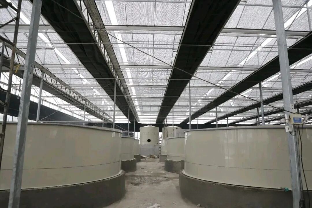
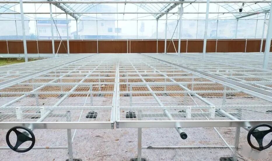
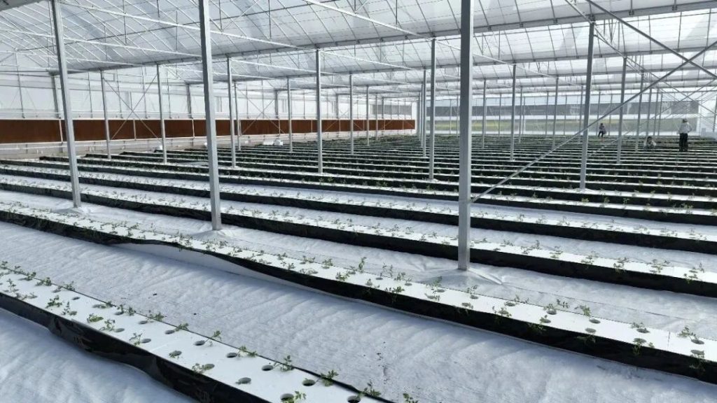
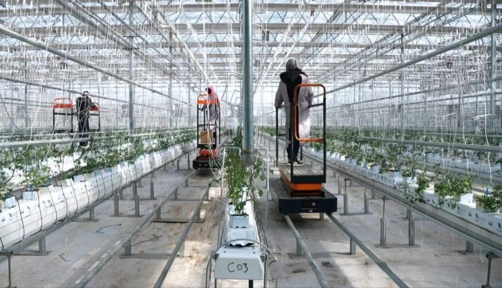
The project covers a standardized planting area of 1,000 square meters (adjustable according to actual site conditions), including a 300 ㎡ flat tidal seedling raising area and a 700 ㎡ three-layer staggered three-dimensional tidal hydroponic planting area. Supporting facilities such as the integrated water and fertilizer system, environmental control system, and electrical automatic control system are fully equipped.

1.2 Construction Content

The main construction works include site foundation and anti-seepage engineering, main planting facility installation engineering, core tidal irrigation system engineering, supporting environmental and electrical system engineering, as well as system commissioning and trial operation.

1.3 Construction Objectives

To realize standardized and automated hydroponic production of leafy vegetables, herbs, fruit and vegetable seedlings and other crops. The water and fertilizer utilization rate reaches ≥95%, the land utilization rate of the three-dimensional planting area is increased by more than 3 times, and the pest and disease incidence is reduced by 60%. The project supports year-round continuous production.

(II) Core Process Description

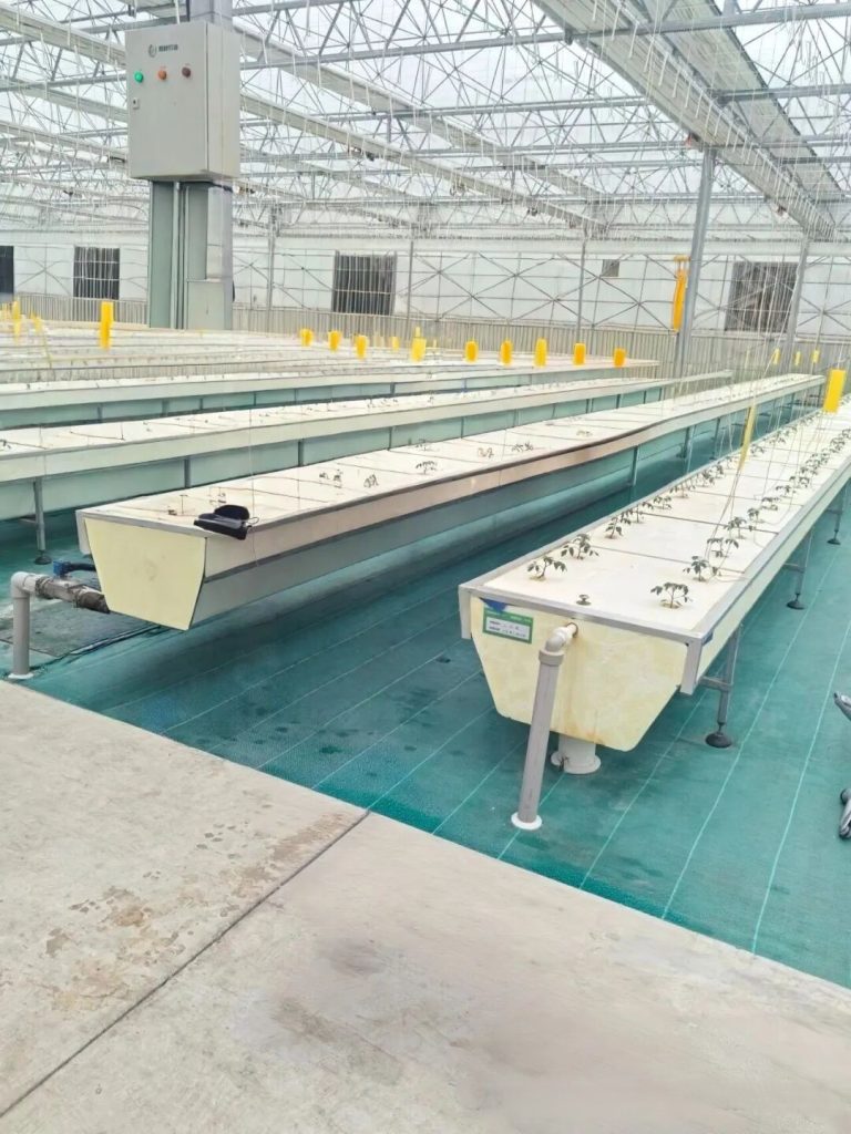
This project adopts the tidal hydroponic technology. Its core working principle relies on a continuous cycle of flooding – water retention – draining. The automatic control system regularly delivers nutrient solution to the planting beds to submerge crop roots and enable full water and fertilizer absorption. After the preset duration is reached, the nutrient solution flows back to the liquid storage tank by gravity, exposing the roots to air for sufficient oxygen intake. This method completely solves the root hypoxia problem common in hydroponic cultivation and features outstanding advantages including water and fertilizer conservation, uniform crop growth, and a high degree of automation.

II. Design Basis and Specifications

1. Code for Design of Greenhouse Structures (GB 51183-2016)
2. Standard for Acceptance of Construction Quality of Steel Structure Engineering (GB 50205-2020)
3. Code for Acceptance of Construction Quality of Building Water Supply, Drainage and Heating Engineering (GB 50242-2002)
4. Code for Design of Low-Voltage Electrical Installations (GB 50054-2011)
5. Code for Installation and Acceptance of Tidal Irrigation System (NY/T 3667-2020)
6. Agricultural Irrigation Equipment — Drip Tubes — Technical Specifications and Test Methods (GB/T 19812.1-2017)
7. Plastic Materials and Products in Contact with Food (GB 4806.7-2016)

III. Overall Construction Deployment

(I) Project Organizational Structure

A project management department shall be established with a complete staffing arrangement, including 1 project manager, 1 technical director, 2 construction supervisors, 1 quality inspector, 1 safety officer and 1 material supervisor. All posts have clear rights and responsibilities to fully control construction quality, progress and safety throughout the whole construction cycle.

(II) Overall Construction Procedure

Site leveling and surveying & setting out → Site foundation and anti-seepage construction → Installation of main planting facilities (seedling beds and three-dimensional supports) → Installation of core pipelines and equipment for tidal irrigation system → Installation of supporting environmental, electrical and automatic control systems → Phased commissioning of individual systems → Whole-system linkage commissioning with clean water trial operation → Water and fertilizer linkage trial operation → Trial planting verification → Completion acceptance and project delivery.

(III) Construction Schedule (Example for 1,000 ㎡ Project)

(To be supplemented according to actual project arrangement)

IV. Construction Technology and Requirements for Key Sub-projects

(I) Site Foundation and Anti-seepage Engineering

As the fundamental guarantee for the stable operation of the tidal irrigation system, this project focuses on three core indicators: surface flatness, drainage gradient and anti-seepage performance.
1. Surveying and Setting Out
In accordance with construction drawings, a total station shall be adopted to locate the boundary of the planting area, the trend of drainage ditches and the position of equipment foundations. Elevation benchmark points shall be set and rechecked throughout the construction process, with the overall error controlled within ±5mm.
2. Site Leveling and Gradient Adjustment
  • The original soil of the planting area shall be compacted, with the compaction coefficient ≥ 0.93 to avoid obvious settlement.
  • A uniform drainage gradient of 0.3%–0.5% shall be formed towards the main drainage ditch, and reverse gradient is strictly prohibited.
  • A C20 fine aggregate concrete leveling layer with a thickness of no less than 50mm shall be poured, with the flatness error not exceeding 3mm per 2-meter measuring distance.
3. Anti-seepage and Surface Treatment
  • After the leveling layer is fully dried, two coats of epoxy anti-seepage coating (total thickness ≥ 0.8mm) shall be applied, or an HDPE anti-seepage membrane (thickness ≥ 1.0mm) shall be laid. The overlapping width of the membrane shall be no less than 100mm with fully fused hot-melt welding to ensure no damage and leakage.
  • The surface shall be treated with anti-slip and wear-resistant measures, such as laying anti-slip floor tiles or making wear-resistant steel sand flooring, to prevent slipping in long-term humid environments.
4. Drainage System Construction
  • Main drainage ditches (300mm wide × 200mm deep) shall be arranged around the planting area, and branch drainage ditches shall be connected with seedling bed drainage outlets with a gradient ≥ 0.5%. All ditches shall be treated with anti-seepage protection.
  • A collecting well shall be installed at the end of the drainage ditch, equipped with grille filters to intercept root residues and impurities. The well body shall be treated with anti-seepage and anti-corrosion measures and fitted with liquid level monitoring devices.


II. Design Basis and Specifications

1. Code for Design of Greenhouse Structures (GB 51183-2016)
2. Standard for Acceptance of Construction Quality of Steel Structure Engineering (GB 50205-2020)
3. Code for Acceptance of Construction Quality of Building Water Supply, Drainage and Heating Engineering (GB 50242-2002)
4. Code for Design of Low-Voltage Electrical Installations (GB 50054-2011)
5. Code for Installation and Acceptance of Tidal Irrigation System (NY/T 3667-2020)
6.Agricultural Irrigation Equipment — Drip Tubes — Technical Specifications and Test Methods (GB/T 19812.1-2017)
7. Plastic Materials and Products in Contact with Food (GB 4806.7-2016)

III. Overall Construction Deployment

(I) Project Organizational Structure

A project management department shall be established with a complete staffing arrangement, including 1 project manager, 1 technical director, 2 construction supervisors, 1 quality inspector, 1 safety officer and 1 material supervisor. All posts have clear rights and responsibilities to fully control construction quality, progress and safety throughout the whole construction cycle.

(II) Overall Construction Procedure

Site leveling and surveying & setting out → Site foundation and anti-seepage construction → Installation of main planting facilities (seedling beds and three-dimensional supports) → Installation of core pipelines and equipment for tidal irrigation system → Installation of supporting environmental, electrical and automatic control systems → Phased commissioning of individual systems → Whole-system linkage commissioning with clean water trial operation → Water and fertilizer linkage trial operation → Trial planting verification → Completion acceptance and project delivery.

(III) Construction Schedule (Example for 1,000 ㎡ Project)

(To be supplemented according to actual project arrangement)

IV. Construction Technology and Requirements for Key Sub-projects

(I) Site Foundation and Anti-seepage Engineering

As the fundamental guarantee for the stable operation of the tidal irrigation system, this project focuses on three core indicators: surface flatness, drainage gradient and anti-seepage performance.
1. Surveying and Setting Out
In accordance with construction drawings, a total station shall be adopted to locate the boundary of the planting area, the trend of drainage ditches and the position of equipment foundations. Elevation benchmark points shall be set and rechecked throughout the construction process, with the overall error controlled within ±5mm.
2. Site Leveling and Gradient Adjustment
  • The original soil of the planting area shall be compacted, with the compaction coefficient ≥ 0.93 to avoid obvious settlement.
  • A uniform drainage gradient of 0.3%–0.5% shall be formed towards the main drainage ditch, and reverse gradient is strictly prohibited.
  • A C20 fine aggregate concrete leveling layer with a thickness of no less than 50mm shall be poured, with the flatness error not exceeding 3mm per 2-meter measuring distance.
3. Anti-seepage and Surface Treatment
  • After the leveling layer is fully dried, two coats of epoxy anti-seepage coating (total thickness ≥ 0.8mm) shall be applied, or an HDPE anti-seepage membrane (thickness ≥ 1.0mm) shall be laid. The overlapping width of the membrane shall be no less than 100mm with fully fused hot-melt welding to ensure no damage and leakage.
  • The surface shall be treated with anti-slip and wear-resistant measures, such as laying anti-slip floor tiles or making wear-resistant steel sand flooring, to prevent slipping in long-term humid environments.
4. Drainage System Construction
  • Main drainage ditches (300mm wide × 200mm deep) shall be arranged around the planting area, and branch drainage ditches shall be connected with seedling bed drainage outlets with a gradient ≥ 0.5%. All ditches shall be treated with anti-seepage protection.
  • A collecting well shall be installed at the end of the drainage ditch, equipped with grille filters to intercept root residues and impurities. The well body shall be treated with anti-seepage and anti-corrosion measures and fitted with liquid level monitoring devices.

(II) Main Planting Facility Installation Engineering

This project consists of two core facilities: flat tidal seedling beds and three-layer staggered three-dimensional tidal planting racks. Serving as the core carriers for hydroponic cultivation, the construction focuses on four key indicators: installation accuracy, load-bearing capacity, leakage prevention and overturning resistance.
1. General Material Requirements
  • Load-bearing supports: Adopt Q235B hot-dip galvanized steel pipes with a wall thickness of ≥2.0mm and a zinc layer thickness of ≥85μm. The materials feature excellent anti-corrosion and rust-proof performance, complying with the service requirements of humid agricultural environments.
  • Tidal planting bed trays: Made of food-grade PP/ABS materials with a thickness of ≥3.5mm, conforming to the standard of GB 4806.7-2016. The trays are acid and alkali resistant, aging resistant and leak-proof, with built-in water level limit clamping grooves and a surface flatness error of ≤2mm/m.
  • Accessories: All connecting parts and bolts are made of 304 stainless steel for corrosion resistance. The rolling wheels adopt brake-locking nylon universal wheels with a single load-bearing capacity of ≥100kg.
2. Installation Technology for Flat Tidal Seedling Beds
  • 1) Setting out and positioning: Determine the installation position of seedling beds and mark column fixing points in accordance with construction drawings. Reserve a 600-800mm operating channel between adjacent seedling beds.
  • 2) Support installation: Install bottom columns and cross beams, and adjust the verticality of columns with an error of ≤1‰ and the horizontality of cross beams with an error of ≤2mm/m. Ensure all components are firmly fixed without looseness.
  • 3) Seedling bed tray installation: Place the planting trays stably on the cross beams, and seal all splicing joints with special sealing strips to eliminate leakage gaps.
  • 4) Leveling and limiting: Adjust the overall horizontality of the seedling bed to an error of ≤±2mm/m. Install transverse movement limiting devices to prevent sliding and anti-overturning fasteners for structural stability.
  • 5) Drainage interface installation: Install drainage and return water interfaces at the lowest point of the seedling bed, equipped with special sealing plugs and filter screens. Ensure airtight connection between interfaces and return water pipelines.
3. Installation Technology for Three-layer Staggered Three-dimensional Tidal Planting Racks (Core Special Process)
  • 1) Setting out and positioning: Mark the installation points of planting racks as per construction drawings. Each rack unit has a standard width of 1200mm and customizable length (conventional length: 3000mm). Reserve an 800mm operating channel between rack units and mark anchor points for column fixation.
  • 2) Main frame installation Install bottom load-bearing columns adopting 80×40×2.0mm hot-dip galvanized rectangular pipes, which are fixed on the concrete floor with no less than 2 expansion bolts for each fixing point. Install vertical diagonal braces and transverse connecting rods to form a stable frame structure. Control the column verticality error within ≤1‰ and the overall transverse and longitudinal horizontality error of the frame within ≤3mm/m. The three-layer frame adopts a staggered layered design, with adjacent upper and lower layers transversely staggered by 300-500mm to ensure uniform light irradiation for lower layers. The layer spacing is adjustable, with conventional heights of 600mm (bottom layer from ground), 1300mm (middle layer) and 2000mm (upper layer), adapting to manual operation and crop growth height requirements.
  • 3) Layered planting tray installation Install tidal planting trays layer by layer after the completion of each layer’s cross beam construction. Fix trays to cross beams with special buckles to prevent displacement. Each layer is independently equipped with a water inlet and a water return port. The water inlet is fitted with a slow-flow device to avoid nutrient solution impact; the water return port is equipped with a two-stage filter screen to intercept root residues and a water level limit valve to precisely control the flooding water level (conventional tidal water level: 50-100mm, adjustable according to crop types). Seal all splicing joints with food-grade sealant, and conduct a 24-hour water tightness test with zero leakage as the acceptance standard.
  • 4) Safety protection installation Install anti-overturning tie rods at the top of each rack, and connect multiple rack units as a whole with transverse connecting rods to enhance overall structural stability. Set 100mm-high edge baffles on each planting tray to prevent nutrient solution overflow. Install grounding devices at the bottom of racks for anti-static and lightning protection treatment.


(III) Construction Engineering of Core Tidal Irrigation System

As the core component of tidal hydroponic cultivation, the system consists of five major modules: water supply system, water return system, water and fertilizer integration system, filtration and disinfection system, and automatic control system. The construction focuses on four key indicators: cycle stability, water and fertilizer accuracy, anti-clogging performance, and disease transmission prevention.
1. Construction of Nutrient Solution Storage Tank
  • The storage tank is constructed of reinforced concrete or adopts food-grade PE finished tank. The volume is designed to be 1.2–1.5 times the total water demand of the planting area. For a standard 1,000 ㎡ planting area, the total configured volume is no less than 20m³, divided into clean water tank, mother liquid tank and circulating nutrient solution tank.
  • The inner wall of the tank is treated with epoxy resin for anti-seepage and anti-corrosion. The tank is equipped with high and low liquid level sensors, temperature sensors, overflow ports, drain ports and manholes. The top of the tank is fully covered and sealed to avoid light exposure and algae growth.
  • A stirring device is installed inside the circulating tank to ensure uniform mixing of nutrient solution. Heating and refrigerating devices are equipped to maintain the nutrient solution temperature at 18–22 ℃, which optimizes root growth conditions for crops.
2. Pipeline System Installation
  • Pipe material selection: UPVC water supply pipes (PN1.0MPa) are adopted for main water supply pipelines; UPVC drainage pipes are used for main return water pipelines; PE pipes are applied for branch pipelines. All pipes are acid and alkali resistant and corrosion resistant, adapting to long-term nutrient solution environment.
  • Pipe laying: Main pipelines are laid along the perimeter trench of the planting area, and branch pipelines are arranged layer by layer along the three-dimensional planting racks with neat and firm installation. The gradient of water supply pipelines is ≥0.002, and the gradient of return water pipelines is ≥0.005. Reverse slope is strictly prohibited. Air relief valves are installed at the highest points to avoid air blockage, and drain valves are arranged at the lowest points for emptying and maintenance.
  • Interface treatment: Special UPVC adhesive is used for bonding connections; hot-melt joints are fully welded without virtual welding or cracks. A hydraulic pressure test shall be conducted after installation: test pressure of 0.6MPa with 30-minute pressure holding, qualified with pressure drop ≤0.05MPa and zero leakage.
3. Core Equipment Installation
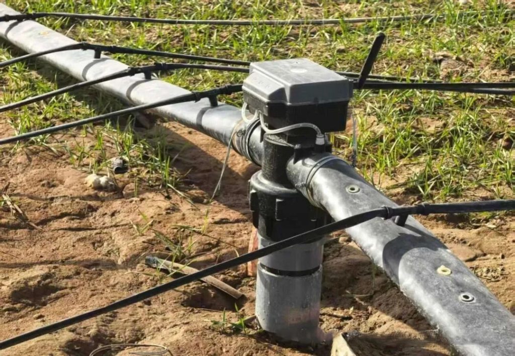
  • 1) Water Supply and Return System Corrosion-resistant centrifugal pumps are adopted for water supply with flow and head matched according to planting scale, configured with one working pump and one standby pump. Shock-absorbing bases and flexible connections are installed to reduce operating noise. The return water system adopts gravity drainage as the main mode and power-assisted drainage as the auxiliary mode. Return water pipelines are hermetically connected to the storage tank with check valves installed to prevent nutrient solution backflow. Each planting branch is equipped with an independent solenoid valve, which is centrally controlled by the automatic system to realize zoned tidal circulation.
  • 2) Filtration and Disinfection System A three-stage filtration system is installed at the water return terminal: 100-mesh grille filter → 120-mesh screen filter → 150-mesh disc filter, which completely intercepts root residues and impurities to prevent blockage of pipelines and solenoid valves. The disinfection system is equipped with a flow-through UV sterilizer (sterilization rate ≥99%) and an ozone disinfection device to eliminate pathogens in nutrient solution, prevent water-borne diseases and avoid continuous cropping obstacles. The UV equipment is installed at the water return end with light-shielding protection.
  • 3) Water and Fertilizer Integration System Equipped with A/B mother liquid tanks and acid liquid tank with volume matched to planting scale, together with a high-precision water and fertilizer integrated machine. The accuracy of EC/PH sensors reaches ≥0.01mS/cm and ±0.05PH respectively. The system realizes automatic nutrient solution proportioning and precisely controls EC value (conventional 1.2–1.8mS/cm for leafy vegetables) and PH value (5.5–6.5), with liquid shortage alarm and overload protection functions. Sensors are installed at the inlet of the circulating tank to avoid water impact damage and calibrated regularly to ensure accurate data monitoring.
  • 4) Automatic Control System Equipped with PLC control cabinet and touch screen, matched with IoT cloud platform to support local and remote dual control. Core control logic supports customizable water inflow duration, water retention duration and drainage duration. The standard circulation cycle is set as 10–15 minutes water inflow → 15–20 minutes water retention → 10–15 minutes drainage, circulating 2–4 times daily, adjustable according to crop varieties and growth stages. The system is equipped with alarm functions for abnormal liquid level, over-limit EC/PH values, pump failure and filter blockage. All operating data can be stored and exported in real time to realize unattended operation.
(IV) Auxiliary System Installation Engineering

1. Environmental Control System
The planting area is equipped with ventilators, wet curtain cooling systems, warm air blowers, temperature & humidity and CO₂ sensors, which are linked with the automatic control system. The system stably controls the indoor environment at temperature 18–28 ℃, humidity 60%–80%, and CO₂ concentration 800–1000ppm to meet crop growth requirements.
2. Supplementary Lighting System
Each layer of the three-layer staggered three-dimensional planting rack is equipped with full-spectrum LED plant grow lights with power of 100–150W/㎡ and illumination intensity of 20,000–30,000lux. The lighting duration can be automatically adjusted according to crop demand through linkage with the control system, effectively compensating insufficient light on lower layers.
3. Electrical System
All electrical equipment adopts waterproof type, and distribution boxes reach IP65 protection level, installed in dry and ventilated areas. The system is configured with leakage protection, overload protection and grounding protection, with grounding resistance ≤4Ω. Flame-retardant and waterproof cables are used in humid areas, and all threading pipes are fully sealed to eliminate potential electrical safety hazards.

V. Quality Control Measures

1. Material Inspection and Acceptance: All incoming materials and equipment must be accompanied by qualification certificates, test reports and quality guarantee documents. Key equipment including water and fertilizer integrated machines, water pumps and sensors shall provide factory calibration reports. Unqualified materials are strictly prohibited from entering the construction site.
2. Phased Quality Control: Each sub-project shall be inspected and accepted by quality inspectors in accordance with specifications before proceeding to the next construction procedure. Key inspection items include foundation flatness, frame verticality, seedling bed horizontality, pipeline hydraulic tests, water tightness tests and electrical insulation tests.
3. Supervision on Key Procedures: Technical supervisors shall conduct full-time on-site supervision during key construction procedures including anti-seepage coating construction, pipeline welding, equipment installation and automatic system wiring to ensure full compliance with design standards.
4. Finished Product Protection: Installed seedling beds, equipment and pipelines shall be properly protected. Treading, impact and damage to coating, pipelines and equipment are strictly prohibited.

VI. Safety Construction, Civilized Construction and Environmental Protection Measures

(I) Safety Construction Measures

1. Conduct safety and technical disclosure for all construction personnel before construction. Special operators such as welders and electricians must hold valid certificates for operation.
2. Safety belts and operating platforms are mandatory for high-altitude operation (upper-layer installation of three-dimensional racks). Throwing objects from height is strictly prohibited.
3. Temporary power supply adopts the standard of three-level power distribution and two-level protection. Distribution boxes are locked, random wiring is forbidden, and 36V safe voltage is applied for operation in humid environments.
4. Fire extinguishers, fire sand and other fire-fighting equipment are equipped on site. Open fire operation and flammable material stacking in the same area are prohibited.
5. Clean the construction site, cut off power and water supply after daily construction to eliminate potential safety hazards.

(II) Civilized Construction and Environmental Protection Measures

1. All materials on site shall be stacked neatly, and construction waste shall be cleaned daily without random dumping.
2. Construction noise is strictly controlled, and high-noise operation at night is forbidden to reduce environmental impact.
3. Construction wastewater shall be precipitated before discharge. Direct discharge of sediment-laden and glue-containing wastewater is prohibited.
4. The system adopts closed-loop nutrient solution circulation with zero discharge. Waste substrates and crop residues are classified and recycled to meet environmental protection standards.

VII. System Commissioning and Trial Operation

(I) Phased Individual Commissioning

After the completion of each system installation, independent commissioning shall be carried out separately: test the on-off and protection functions of the electrical system; verify the start-stop, flow and head performance of water pumps; check the switching sensitivity of solenoid valves; calibrate the data acquisition accuracy of sensors; test the logic control and alarm functions of the automatic system. Overall linkage commissioning can only be launched after all individual items pass inspection.

(II) Clean Water Linkage Trial Operation

1. Fill the storage tank with clean water and launch the full-process tidal circulation test for continuous 72-hour operation.
2. Key inspection items include tidal inflow and drainage time control, water level accuracy, pipeline and seedling bed tightness, drainage smoothness, filter anti-clogging performance, system operating stability and normal alarm response.
3. Rectify all problems found during trial operation and conduct repeated tests until the whole system operates stably with zero faults.

(III) Water-Fertilizer Linkage Test and Trial Planting Verification

1. After qualified clean water trial operation, prepare nutrient solution according to crop formulas, debug the water and fertilizer integrated machine and calibrate EC/PH values. Conduct 48-hour continuous water-fertilizer linkage trial operation, which is deemed qualified with stable nutrient solution proportioning and no abnormal operation.
2. Carry out trial planting including seedling raising and transplanting of target crops. Monitor system operation status and crop growth conditions in real time, and optimize tidal circulation parameters and water-fertilizer indicators. Launch final completion acceptance after the system operates stably and crops grow normally.

VIII. Completion Acceptance and Project Delivery

1. After completing all construction works and qualified system trial operation, the construction party shall submit completion acceptance application to the project owner, together with complete completion documents including as-built drawings, material and equipment qualification certificates, test reports, construction records, commissioning reports, trial operation records and operation & maintenance manuals.
2. The project owner organizes joint acceptance by the design institute, construction unit and supervision unit to comprehensively inspect on-site construction quality and system operating performance in accordance with design drawings and industry specifications.
3. After qualified acceptance, sign the completion acceptance report and complete project delivery procedures. Conduct professional operation and maintenance technical disclosure and personnel training for the owner to ensure long-term stable system operation.

IX. Appendix: Operation and Maintenance Management Guidelines

1. Daily Inspection: Check system operating status, liquid level, EC/PH values, pipeline tightness and filter pressure difference daily, and clean blocked filters in a timely manner.
2. Regular Maintenance: Calibrate EC/PH sensors weekly; clean and disinfect pipelines and seedling beds monthly; inspect and maintain water pumps, valves and electrical equipment quarterly.
3. Nutrient Solution Management: Regularly detect nutrient solution components and supplement nutrients timely. Completely replace the nutrient solution and conduct full-system cleaning and disinfection after each crop harvest to prevent disease cross-infection.
4. Equipment Management: Establish complete equipment ledgers to record operation, maintenance and overhaul records. Prepare sufficient spare parts for vulnerable components to ensure continuous and stable system operation.